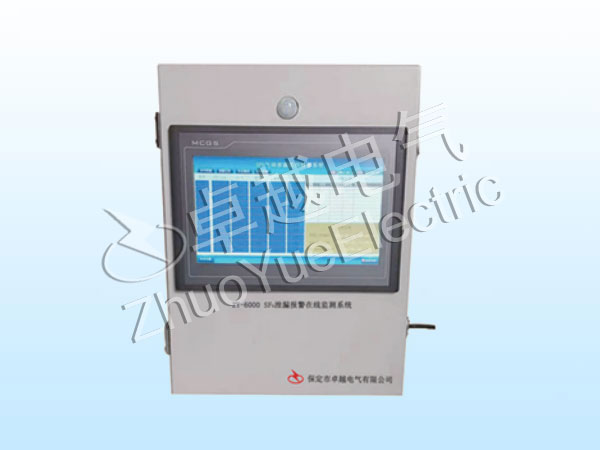
1.System Overview
The ZY-6000 SF6 Leakage Alarm Online Monitoring System is an online monitoring and alarm system for SF6 insulation gas leakage of indoor SF6 composite electrical equipment in a new unmanned substation. The system adopts new sensor technology, which can quantitatively and real-time measure the SF6 leakage gas content online, with high measurement accuracy, remote data transmission, and convenient installation and use. This system provides multi-point monitoring of indoor SF6 and O2 concentrations, environmental temperature, and humidity, with up to 128 monitoring points. The use of this system can not only achieve the goal of ensuring personal safety and providing more protection for on-site workers, but also ensure the normal operation of the equipment.
2.Product Features
● Testing principles
This system uses NDIR sensors. Infrared sensors have the characteristics of long lifespan, stable and reliable operation, non-contact, minimal environmental impact, and strong anti-interference, making them very suitable for online monitoring products.
● Multiple detection function
This system provides dual detection for SF6 and oxygen, effectively ensuring the safety of the working environment for staff and reflecting the people-oriented work philosophy of the enterprise.
● Fieldbus design
Fieldbus design facilitates communication between users and various systems, achieving seamless connection.
● Historical data recording and querying
This system can continuously store all data within one year for reference and curve analysis.
● Voice and infrared functions
This system supports infrared human body detection, automatically starts the fan or voice prompts, and broadcasts the on-site situation through voice. Staff can receive voice prompts when approaching dangerous environments without any operation.
● Data upload cloud platform
After uploading on-site data to the cloud platform, it can be viewed by multiple computer and mobile terminals.
Alarm output: Relay empty contact output, can be connected to RTU, and supports RS485 alarm output.
● Support remote start of fan function.
Fan controller: switch type: directly control the fan power supply; Pulse type: connected to the fan control switch. Optional according to on-site conditions.
The fan startup supports multiple modes: timed start, alarm start, automatic start when there are people, remote start, manual start, etc.
● Support remote transmission and output of measurement data through RS485, such as installing a large LED display screen at the entrance, where measurement parameters and system operation can be immediately seen from afar. (To be selected by the user separately)
3. Technical parameters
Measurement range: 0-3000ppm
SF6 measurement accuracy: ± 2% FS
SF6 detection principle: dual wave infrared detection (NDIR)
Oxygen detection concentration: 0-25%
Oxygen measurement accuracy: ± 0.5%
Oxygen detection principle: electrochemical
Number of sensors: 5 as standard (expandable to 128)
Hypoxia alarm threshold: 18.0% (adjustable)
Pressure range: 800hPa-1000hPa
Temperature range: -20 to 125 ℃
Humidity range: 0% -99% Relative humidity Working power supply:~(100V~240V)
Power: 50W
4. System topology

5. Operation instructions
Real-time data display
After the system is powered on and initialized, the real-time data page is displayed, showing the current SF6, O2, temperature, humidity, and status of all measurement channels (Normal: black; Alarm: red;) The operation of the fan is shown in the following figure.

System settings
Click on System Settings and a user login dialog box will pop up.

Enter the correct username and password, click OK to enter the system settings interface, as shown in the following figure

After setting the parameters, click Save and a confirmation dialog box will pop up. Click OK to save the set parameters.
Sensor calibration method setting
Click on automatic calibration in the above interface to set the sensor calibration method to manual calibration, as shown in the following figure

At this point, click Calibrate to calibrate the sensor. Clicking on manual calibration in this mode will return to the automatic calibration status.
6. Installation dimensions


 首頁
首頁 咨詢
咨詢 產(chǎn)品